ENIB 2022 - groupe B : Labyrinthe
Sommaire
photo de l'équipe
Que fait ce projet ?
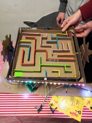
Le but de ce projet est de diriger une bille dans un labyrinthe en jouant avec son inclinaison à l'aide de servo-moteurs et de deux potentiomètres comme actionneurs.
Liste des composants
- carte WIMOS D1 mini
- servo-moteur x2
- potentiomètre angulaire x2
- câbles
- bande de LED
- carton rigide
- stickers
- bille
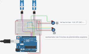
Circuit
Code
Ce projet n'a en final pas été bien fonctionnel, ceci est peut-être et surement en partie du au code.

#include <Servo.h>
#include <FastLED.h>  //bibliothèque FastLED, utilisation d'un exemple donné

// Pride2015
// Animated, ever-changing rainbows.
// by Mark Kriegsman

#if FASTLED_VERSION < 3001000
#error "Requires FastLED 3.1 or later; check github for latest code."
#endif

#define DATA_PIN    D7      //PIN d'entré
//#define CLK_PIN   4
#define LED_TYPE    WS2812  //type de LED
#define COLOR_ORDER GRB
#define NUM_LEDS    20      //nombre de LED
#define BRIGHTNESS  255     //luminosité

CRGB leds[NUM_LEDS];


Servo Xesc;                       //servo moteur axe X
int Xval;                         //potentiomètre axe X
int XPinCLK = D1;
int XPinDT = D2;
static long XencoderPos = 45;     //position initiale de l'encodeur
int XPinCLKLast = LOW;
int XnbPas = 90;                 // Résolution de l'encodeur
int Xn = LOW;


Servo Yesc;                       //servo moteur axe Y
int Yval;                         //potentiomètre axe Y
int YPinCLK = D3;
int YPinDT = D4;
static long YencoderPos = 45;     //position initiale de l'encodeur
int YPinCLKLast = LOW;
int YnbPas = 90;                 // Résolution de l'encodeur
int Yn = LOW;

void setup() {
  pinMode (XPinCLK,INPUT);      //servo moteur et potentiomètre axe X
  pinMode (XPinDT,INPUT);
  Xesc.attach(D5);

  pinMode (YPinCLK,INPUT);      //servo moteur et potentiomètre axe Y
  pinMode (YPinDT,INPUT);
  Yesc.attach(D6);
  Serial.begin (9600);
  delay(3000);

  FastLED.addLeds<LED_TYPE,DATA_PIN,COLOR_ORDER>(leds, NUM_LEDS)
    .setCorrection(TypicalLEDStrip)
    .setDither(BRIGHTNESS < 255);

  FastLED.setBrightness(BRIGHTNESS);
}


void loop() {
   Xn = digitalRead(XPinCLK);                            //servo moteur axe X

   if ((XPinCLKLast == LOW) && (Xn == HIGH)) {      //détermination du sens de rotation

     if (digitalRead(XPinDT) == LOW) {
       Serial.print("Sens antihoraire, position ");
       XencoderPos--;
       if ( XencoderPos < (XnbPas/2-XnbPas/18) ) {      //angle maximal
         XencoderPos = (XnbPas/2-XnbPas/18);
       }
     } else {
       Serial.print("Sens horaire, position ");
       XencoderPos++;
       if ( XencoderPos > (XnbPas/2+XnbPas/18) ) {      //angle maximal
         XencoderPos = (XnbPas/2+XnbPas/18);
       }
     }
     Serial.print (XencoderPos); Serial.print(", angle "); Serial.println( abs ( XencoderPos * ( 360 / XnbPas ) ));     //affichage des valeurs
     //Serial.print ("/");
     Xesc.write(abs ( XencoderPos * ( 360 / XnbPas ) ));    //position du servo moteur

   }
   XPinCLKLast = Xn;

   Yn = digitalRead(YPinCLK);                            //servo moteur axe Y

   if ((YPinCLKLast == LOW) && (Yn == HIGH)) {      //détermination du sens de rotation

     if (digitalRead(YPinDT) == LOW) {
       Serial.print("Sens antihoraire, position ");
       YencoderPos--;
       if ( YencoderPos < (YnbPas/2-YnbPas/18) ) {      //angle maximal
         YencoderPos = (YnbPas/2-YnbPas/18);
       }
     } else {
       Serial.print("Sens horaire, position ");
       YencoderPos++;
       if ( YencoderPos > (YnbPas/2+YnbPas/18) ) {      //angle maximal
         YencoderPos = (YnbPas/2+YnbPas/18);
       }
     }
     Serial.print (YencoderPos); Serial.print(", angle "); Serial.println( abs ( YencoderPos * ( 360 / YnbPas ) ));     //affichage des valeurs
     //Serial.print ("/");
     Yesc.write(abs ( YencoderPos * ( 360 / YnbPas ) ));    //position du servo moteur

   }
   YPinCLKLast = Yn;

   pride();                 //lancement des LED
   FastLED.show();

 }


// This function draws rainbows with an ever-changing,
// widely-varying set of parameters.
void pride()
{
  static uint16_t sPseudotime = 0;
  static uint16_t sLastMillis = 0;
  static uint16_t sHue16 = 0;

  uint8_t sat8 = beatsin88( 87, 220, 250);
  uint8_t brightdepth = beatsin88( 341, 96, 224);
  uint16_t brightnessthetainc16 = beatsin88( 203, (25 * 256), (40 * 256));
  uint8_t msmultiplier = beatsin88(147, 23, 60);

  uint16_t hue16 = sHue16;//gHue * 256;
  uint16_t hueinc16 = beatsin88(113, 1, 3000);

  uint16_t ms = millis();
  uint16_t deltams = ms - sLastMillis ;
  sLastMillis  = ms;
  sPseudotime += deltams * msmultiplier;
  sHue16 += deltams * beatsin88( 400, 5,9);
  uint16_t brightnesstheta16 = sPseudotime;

  for( uint16_t i = 0 ; i < NUM_LEDS; i++) {
    hue16 += hueinc16;
    uint8_t hue8 = hue16 / 256;

    brightnesstheta16  += brightnessthetainc16;
    uint16_t b16 = sin16( brightnesstheta16  ) + 32768;

    uint16_t bri16 = (uint32_t)((uint32_t)b16 * (uint32_t)b16) / 65536;
    uint8_t bri8 = (uint32_t)(((uint32_t)bri16) * brightdepth) / 65536;
    bri8 += (255 - brightdepth);

    CRGB newcolor = CHSV( hue8, sat8, bri8);

    uint16_t pixelnumber = i;
    pixelnumber = (NUM_LEDS-1) - pixelnumber;

    nblend( leds[pixelnumber], newcolor, 64);
  }
}
possibilités d'amélioration
Le projet n'a été en final pas vraiment fonctionnel, ceci et peut être dû en la structure trop légère. Pour améliorer ce point et avoir un aspect plus finit elle pourrait être faite en bois, a la découpeuse laser. Il faudrait aussi et surement modifier le code en faisant des test sur les servo-moteurs individuellement. Pour finir, la partie électronique avec les fils pourrait être caché dans un boîtier.
documentation
Utilisation d'une carte WeMos D1 mini
Comprendre le fonctionnement d'un potentiomètre angulaire ainsi que la structure du code du projet.
Comprendre le fonctionnement d'un servomoteur


