ENIB 2024 : Smash The Button
Titre de la fiche expérience :
Sommaire
Description
Notre équipe est composée de 4 membres : Samuel, Mathieu, Loane et Maïa.
Mettre image avec projet fini test//
Introduction
éventuelle vidéo
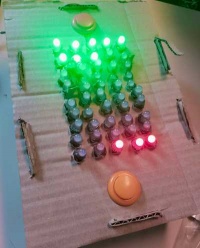
Le nom de notre jeu est Smash The Button. Il s’agit d’un jeu en un contre un. Le but est de conquérir un maximum de territoire en un minimum de temps. Le vainqueur est celui ayant le plus grand territoire.
Outil et matériel
Nous avons utilisé comme matériel un WS2811 LED Strip (permettant d’obtenir un grand nombre de LED), deux boutons poussoirs l’un rouge l’autre jaune, une carte Arduino Nano, un buzzer, une batterie externe et un bouton pour lancer le jeu.
Fichiers à joindre
code, ficher d'impression 3D, de découpe laser ou vinyle, ...
Code Arduino
  1
  2 #include <FastLED.h>
  3
  4 #define LED_PIN 5
  5
  6 #define BUZZER_PIN 7
  7
  8 #define NUM_LEDS 50
  9
 10 #define BUTTON_PIN1 2
 11
 12 #define BUTTON_PIN2 3
 13
 14 #define DELAY_MS 50
 15
 16 #define RED_BUTTON_FREQ 100 // Frequency for the red button sound
 17
 18 #define GREEN_BUTTON_FREQ 200  // Frequency for the green button sound
 19
 20 CRGB leds[NUM_LEDS];
 21
 22 int ledCount1 = 0; // Number of red LEDs to light up from one end
 23
 24 int ledCount2 = 0; // Number of green LEDs to light up from the other end
 25
 26 bool buttonState1 = false;
 27
 28 bool lastButtonState1 = false;
 29
 30 bool buttonState2 = false;
 31
 32 bool lastButtonState2 = false;
 33
 34 bool isRedButtonPressed = false;
 35
 36 bool isGreenButtonPressed = false;
 37
 38 void setup() {
 39
 40   FastLED.addLeds<WS2812B, LED_PIN, GRB>(leds, NUM_LEDS);
 41
 42   pinMode(BUTTON_PIN1, INPUT_PULLUP);
 43
 44   pinMode(BUTTON_PIN2, INPUT_PULLUP);
 45
 46   pinMode(BUZZER_PIN, OUTPUT);
 47
 48 }
 49
 50 void loop() {
 51
 52   buttonState1 = digitalRead(BUTTON_PIN1) == LOW;
 53
 54   buttonState2 = digitalRead(BUTTON_PIN2) == LOW;
 55
 56   if (buttonState1 != lastButtonState1) {
 57
 58     if (buttonState1) {
 59
 60       // Button 1 is pressed
 61
 62       ledCount1++;
 63
 64       if (ledCount1 > NUM_LEDS) {
 65
 66         ledCount1 = NUM_LEDS;
 67
 68       }
 69
 70       isRedButtonPressed = true;
 71
 72       tone(BUZZER_PIN, RED_BUTTON_FREQ);  // Play the red button sound
 73
 74     }
 75
 76     lastButtonState1 = buttonState1;
 77
 78   }
 79
 80   if (buttonState2 != lastButtonState2) {
 81
 82     if (buttonState2) {
 83
 84       // Button 2 is pressed
 85
 86       ledCount2++;
 87
 88       if (ledCount2 > NUM_LEDS) {
 89
 90         ledCount2 = NUM_LEDS;
 91
 92       }
 93
 94       isGreenButtonPressed = true;
 95
 96       tone(BUZZER_PIN, GREEN_BUTTON_FREQ);  // Play the green button sound
 97
 98     }
 99
100     lastButtonState2 = buttonState2;
101
102   }
103
104
105
106   // Turn off all LEDs
107
108   FastLED.clear();
109
110
111
112   // Light up the specified number of red LEDs from one end
113
114   for (int i = 0; i < ledCount1; i++) {
115
116     leds[i] = CRGB::Green;
117
118   }
119
120
121
122   // Light up the specified number of green LEDs from the other end
123
124   for (int i = NUM_LEDS - 1; i >= NUM_LEDS - ledCount2; i--) {
125
126     leds[i] = CRGB::Red;
127
128   }
129
130
131
132   if ((ledCount1 + ledCount2) >= NUM_LEDS) {
133
134     if (ledCount1 > ledCount2) {
135
136       greenChaserEffect();
137
138     } else if (ledCount2 > ledCount1) {
139
140       redChaserEffect();
141
142     } else {
143
144       // It's a tie
145
146       tieChaserEffect();
147
148     }
149
150
151
152     // Reset the LED counts
153
154     ledCount1 = 0;
155
156     ledCount2 = 0;
157
158   }
159
160
161
162   // Show the updated LED strip
163
164   FastLED.show();
165
166
167
168   if (isRedButtonPressed || isGreenButtonPressed) {
169
170     delay(50); // Adjust this delay to control the duration of the buzzer sound
171
172     noTone(BUZZER_PIN); // Stop the buzzer sound
173
174     isRedButtonPressed = false;
175
176     isGreenButtonPressed = false;
177
178   }
179
180
181
182   delay(50); // Adjust this delay to debounce the buttons and control the response speed
183
184 }
185
186
187
188 void tieChaserEffect() {
189
190
191
192   for (int i = 0; i < NUM_LEDS / 2; i++) {
193
194     leds[i] = CRGB::Red;  // Set the color of the current LED to red
195
196     FastLED.show();       // Update the LED strip
197
198     delay(DELAY_MS);      // Wait for a short period
199
200   }
201
202
203
204   for (int i = NUM_LEDS; i >= NUM_LEDS / 2; i--) {
205
206     leds[i] = CRGB::Green;  // Set the color of the current LED to red
207
208     FastLED.show();       // Update the LED strip
209
210     delay(DELAY_MS);      // Wait for a short period
211
212   }
213
214 }
215
216
217
218 void greenChaserEffect() {
219
220   // Set all LEDs to green initially
221
222   for (int i = 0; i < ledCount1; i++) {
223
224     leds[i] = CRGB::Green;
225
226   }
227
228   FastLED.show();  // Update the LED strip with the initial green color
229
230
231
232   for (int i = ledCount1; i < NUM_LEDS; i++) {
233
234     leds[i] = CRGB::Green;  // Set the color of the current LED to red
235
236     FastLED.show();       // Update the LED strip
237
238     delay(DELAY_MS);      // Wait for a short period
239
240   }
241
242 }
243
244
245
246 void redChaserEffect() {
247
248   // Set all LEDs to green initially
249
250   for (int i = NUM_LEDS - 1; i >= NUM_LEDS - ledCount2; i--) {
251
252     leds[i] = CRGB::Red;
253
254   }
255
256   FastLED.show();  // Update the LED strip with the initial green color
257
258
259
260   for (int i = ledCount2; i > 0; i--) {
261
262     leds[i] = CRGB::Red;  // Set the color of the current LED to red
263
264     FastLED.show();       // Update the LED strip
265
266     delay(DELAY_MS);      // Wait for a short period
267
268   }
269
270 }
Étapes de fabrication
Étape 1
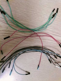
Tout d'abord nous avons fait l'inventaire de ce dont nous avions besoin. Il nous manquait une alimentation, trois câbles rouges, sept câbles noir ou gris et quatre câbles de couleur (vert).
Étape 2
Nous avons commencé avec la partie électronique. Nous avons débuté avec la connexion de la carte à l'ordinateur. Mise en place de carte (communication)
Étape 3
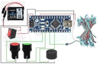
Puis nous avons fait le câblage à l'aide de ce schéma.
Étape 4
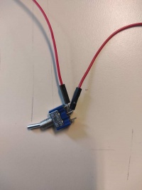
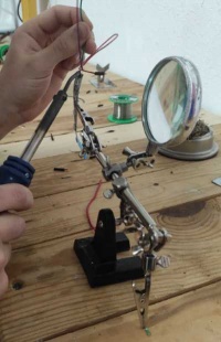
Puis nous avons souder notre câblage afin d'obtenir un rendu propre.
Étape 5
Nous avons choisit le matériau pour faire la patron, nous avons choisit le carton. On a alors dessiné le patron.
Étape 6
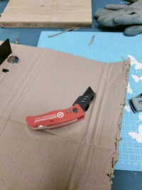
Ensuite, nous sommes passés au découpage.
Étape 7
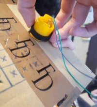
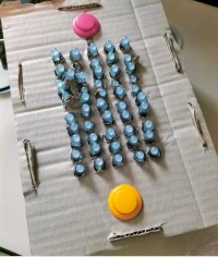
Après, nous sommes passés à l'assemblage. Tout d'abord nous nous sommes occupés des boutons.
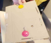
On obtient ceci.
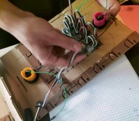
Mise en place des différentes LED sur le support.
Étape 8
On obtient après assemblage, une version éteinte et une version allumée.
Étape 9
Amélioration du projet : mise en place d'un son lors de la partie gagner et mise en place d'un système de point.
Problèmes rencontrés
Nous avons eux un problème de compilation avec la carte Arduino Nano.

