Smartmobile : Différence entre versions
(→Réalisation) |
|||
| (24 révisions intermédiaires par un autre utilisateur non affichées) | |||
| Ligne 35 : | Ligne 35 : | ||
*Percer un trou devant chaque moteur pour laisser passez les câbles | *Percer un trou devant chaque moteur pour laisser passez les câbles | ||
*Souder les fils sur les moteurs | *Souder les fils sur les moteurs | ||
| − | [[Image:smartsoudure.jpg]] | + | [[Image:smartsoudure.jpg|500px]] |
| + | *Pour le cablâge voir vidéo (et faire correspondre les broches avec celle de la wemos): | ||
| + | https://www.youtube.com/watch?v=2AL7HfiRlp4&t=242s | ||
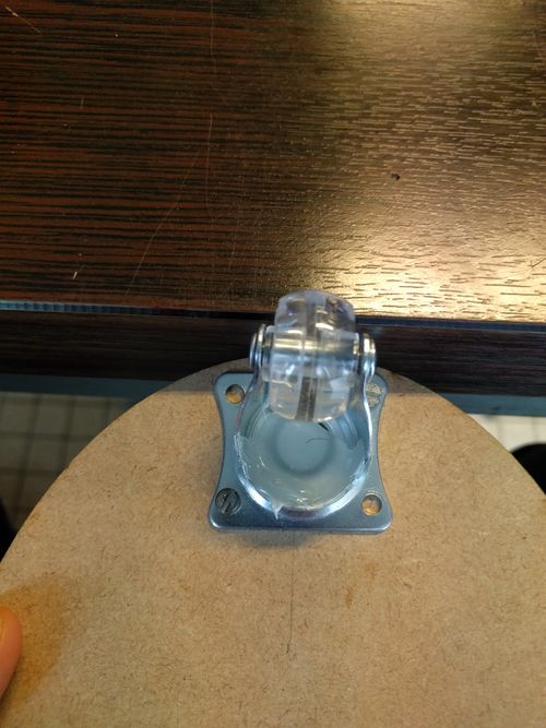
| + | *Vous pouvez mettre de la colle sur la roue pour eviter qu'elle ce coince : | ||
| + | |||
| + | [[Fichier:cacolle.jpg |500px]] | ||
| + | |||
| + | == '''Code''' == | ||
| + | Code pour recupèré l'IP du robot : | ||
| + | |||
| + | <pre>#include <ESP8266WiFi.h> | ||
| + | WiFiClient client; | ||
| + | WiFiServer server(80); | ||
| + | const char* ssid = "Test"; | ||
| + | const char* password = "12345678"; | ||
| + | |||
| + | void setup() | ||
| + | { | ||
| + | Serial.begin(115200); | ||
| + | connectWiFi(); | ||
| + | server.begin(); | ||
| + | } | ||
| + | |||
| + | void loop() | ||
| + | { | ||
| + | |||
| + | } | ||
| + | |||
| + | void connectWiFi() | ||
| + | { | ||
| + | Serial.println("Connecting to WIFI"); | ||
| + | WiFi.begin(ssid, password); | ||
| + | while ((!(WiFi.status() == WL_CONNECTED))) | ||
| + | { | ||
| + | delay(300); | ||
| + | Serial.print(".."); | ||
| + | } | ||
| + | Serial.println(""); | ||
| + | Serial.println("WiFi connected"); | ||
| + | Serial.println("NodeMCU Local IP is : "); | ||
| + | Serial.print((WiFi.localIP())); | ||
| + | } | ||
| + | </pre> | ||
| + | Code permetant de faire fonctionner le robot : | ||
| + | |||
| + | *Pour cela il faut avoir le logiciel arduino et ajouter le pilote ESP8266 pour la carte wemos. | ||
| + | * voici le liens de téléchargement le pilote :(https://wiki.wemos.cc/tutorials:get_started:get_started_in_arduino/). | ||
| + | *installer ensuite de pilote. | ||
| + | |||
| + | <pre> | ||
| + | #include <ESP8266WiFi.h> | ||
| + | |||
| + | |||
| + | /* define port */ | ||
| + | WiFiClient client; | ||
| + | WiFiServer server(80); | ||
| + | |||
| + | /* WIFI settings */ | ||
| + | const char* ssid = "Test"; | ||
| + | const char* password = "12345678"; | ||
| + | |||
| + | /* data received from application */ | ||
| + | String data =""; | ||
| + | |||
| + | /* define L298N or L293D motor control pins */ | ||
| + | int leftMotorForward = 2; /* GPIO2(D4) -> IN3 */ | ||
| + | int rightMotorForward = 15; /* GPIO15(D8) -> IN1 */ | ||
| + | int leftMotorBackward = 0; /* GPIO0(D3) -> IN4 */ | ||
| + | int rightMotorBackward = 13; /* GPIO13(D7) -> IN2 */ | ||
| + | |||
| + | |||
| + | /* define L298N or L293D enable pins */ | ||
| + | int rightMotorENB = 14; /* GPIO14(D5) -> Motor-A Enable */ | ||
| + | int leftMotorENB = 12; /* GPIO12(D6) -> Motor-B Enable */ | ||
| + | |||
| + | void setup() | ||
| + | { | ||
| + | /* initialize motor control pins as output */ | ||
| + | pinMode(leftMotorForward, OUTPUT); | ||
| + | pinMode(rightMotorForward, OUTPUT); | ||
| + | pinMode(leftMotorBackward, OUTPUT); | ||
| + | pinMode(rightMotorBackward, OUTPUT); | ||
| + | |||
| + | /* initialize motor enable pins as output */ | ||
| + | pinMode(leftMotorENB, OUTPUT); | ||
| + | pinMode(rightMotorENB, OUTPUT); | ||
| + | |||
| + | /* start server communication */ | ||
| + | server.begin(); | ||
| + | } | ||
| + | |||
| + | void loop() | ||
| + | { | ||
| + | /* If the server available, run the "checkClient" function */ | ||
| + | client = server.available(); | ||
| + | if (!client) return; | ||
| + | data = checkClient (); | ||
| + | |||
| + | |||
| + | /* If the incoming data is "forward", run the "MotorForward" function */ | ||
| + | if (data == "forward") MotorForward(); | ||
| + | /* If the incoming data is "backward", run the "MotorBackward" function */ | ||
| + | else if (data == "backward") MotorBackward(); | ||
| + | /* If the incoming data is "left", run the "TurnLeft" function */ | ||
| + | else if (data == "left") TurnLeft(); | ||
| + | /* If the incoming data is "right", run the "TurnRight" function */ | ||
| + | else if (data == "right") TurnRight(); | ||
| + | /* If the incoming data is "stop", run the "MotorStop" function */ | ||
| + | else if (data == "stop") MotorStop(); | ||
| + | } | ||
| + | |||
| + | void MotorForward(void) | ||
| + | { | ||
| + | digitalWrite(leftMotorENB,HIGH); | ||
| + | digitalWrite(rightMotorENB,HIGH); | ||
| + | digitalWrite(leftMotorForward,HIGH); | ||
| + | digitalWrite(rightMotorForward,HIGH); | ||
| + | digitalWrite(leftMotorBackward,LOW); | ||
| + | digitalWrite(rightMotorBackward,LOW); | ||
| + | } | ||
| + | |||
| + | void MotorBackward(void) | ||
| + | { | ||
| + | digitalWrite(leftMotorENB,HIGH); | ||
| + | digitalWrite(rightMotorENB,HIGH); | ||
| + | digitalWrite(leftMotorBackward,HIGH); | ||
| + | digitalWrite(rightMotorBackward,HIGH); | ||
| + | digitalWrite(leftMotorForward,LOW); | ||
| + | digitalWrite(rightMotorForward,LOW); | ||
| + | } | ||
| + | |||
| + | |||
| + | void TurnLeft(void) | ||
| + | { | ||
| + | digitalWrite(leftMotorENB,HIGH); | ||
| + | digitalWrite(rightMotorENB,HIGH); | ||
| + | digitalWrite(leftMotorForward,LOW); | ||
| + | digitalWrite(rightMotorForward,HIGH); | ||
| + | digitalWrite(rightMotorBackward,LOW); | ||
| + | digitalWrite(leftMotorBackward,HIGH); | ||
| + | } | ||
| + | |||
| + | |||
| + | void TurnRight(void) | ||
| + | { | ||
| + | digitalWrite(leftMotorENB,HIGH); | ||
| + | digitalWrite(rightMotorENB,HIGH); | ||
| + | digitalWrite(leftMotorForward,HIGH); | ||
| + | digitalWrite(rightMotorForward,LOW); | ||
| + | digitalWrite(rightMotorBackward,HIGH); | ||
| + | digitalWrite(leftMotorBackward,LOW); | ||
| + | } | ||
| + | |||
| + | |||
| + | void MotorStop(void) | ||
| + | { | ||
| + | digitalWrite(leftMotorENB,LOW); | ||
| + | digitalWrite(rightMotorENB,LOW); | ||
| + | digitalWrite(leftMotorForward,LOW); | ||
| + | digitalWrite(leftMotorBackward,LOW); | ||
| + | digitalWrite(rightMotorForward,LOW); | ||
| + | digitalWrite(rightMotorBackward,LOW); | ||
| + | } | ||
| + | |||
| + | String checkClient (void) | ||
| + | { | ||
| + | while(!client.available()) delay(1); | ||
| + | String request = client.readStringUntil('\r'); | ||
| + | request.remove(0, 5); | ||
| + | request.remove(request.length()-9,9); | ||
| + | return request; | ||
| + | } | ||
| + | </pre> | ||
| + | |||
| + | |||
| + | |||
| + | == Téléchargement == | ||
| + | Application android : | ||
| + | [[Fichier:AplliAndroidCommande.zip]] | ||
| + | |||
| + | Dezipper les fichiers et coller les dans votre telephone. | ||
| + | |||
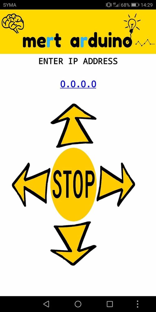
| + | Voila l'interface sur votre téléphone : | ||
| + | |||
| + | [[Fichier:interf.jpg|500px]] | ||
| + | |||
| + | ==catégorie== | ||
| + | [[Catégorie:Arduino]] | ||
| + | [[Catégorie:Robot]] | ||
| + | [[Catégorie:impression 3D]] | ||
| + | [[catégorie:Enib2019]] | ||
| + | [[catégorie:Enib]] | ||
Version actuelle datée du 26 août 2024 à 08:38
Résumé
Le projet consistant en la création d'un véhicule commandé via un smartphone android.
La smartmobile utilise un Wemos pour communiquer avec le smartphone par Wifi.
Matériel
- Une planche en bois
- 2 packs de 3 piles AAA
- Un module Wemos
- Controleur de moteur (https://tronixstuff.com/2014/11/25/tutorial-l298n-dual-motor-controller-modules-and-arduino/)
- Cables
- 2 Motoréducteurs avec roues ( https://fr.aliexpress.com/item/TT-Motor-Voiture-Smart-Robot-Motor-ducteur-pour-arduino-Diy-Kit-Roues-Ch-ssis-De-la/32955649869.html?spm=a2g0s.9042311.0.0.27426c37wg8JSG)
- 1 Roue folle
- Boulons
- Colle
Réalisation
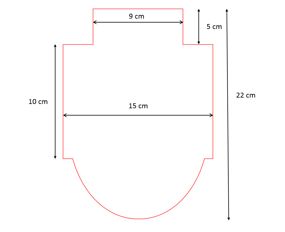
- Decouper la planche de cette façon :
- Percer 2 ou 4 trous devant (au centre) pour fixer la roue.
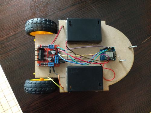
- Coller les blocs de piles sur les cotés et les cartes au millieu (exemple si dessous)
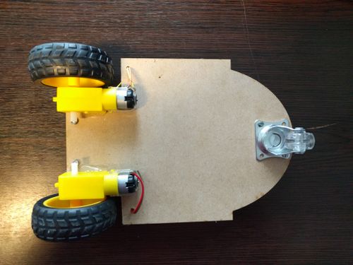
- Coller les moteurs dessous (exemple si dessous)
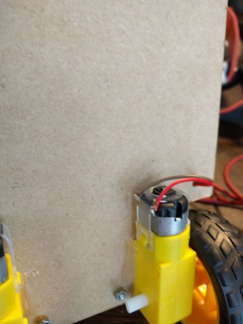
- Percer un trou devant chaque moteur pour laisser passez les câbles
- Souder les fils sur les moteurs
- Pour le cablâge voir vidéo (et faire correspondre les broches avec celle de la wemos):
https://www.youtube.com/watch?v=2AL7HfiRlp4&t=242s
- Vous pouvez mettre de la colle sur la roue pour eviter qu'elle ce coince :
Code
Code pour recupèré l'IP du robot :
#include <ESP8266WiFi.h>
WiFiClient client;
WiFiServer server(80);
const char* ssid = "Test";
const char* password = "12345678";

void setup()
{
  Serial.begin(115200);
  connectWiFi();
  server.begin();
}

void loop()
{

}

void connectWiFi()
{
  Serial.println("Connecting to WIFI");
  WiFi.begin(ssid, password);
  while ((!(WiFi.status() == WL_CONNECTED)))
  {
    delay(300);
    Serial.print("..");
  }
  Serial.println("");
  Serial.println("WiFi connected");
  Serial.println("NodeMCU Local IP is : ");
  Serial.print((WiFi.localIP()));
}
Code permetant de faire fonctionner le robot :
- Pour cela il faut avoir le logiciel arduino et ajouter le pilote ESP8266 pour la carte wemos.
- voici le liens de téléchargement le pilote :(https://wiki.wemos.cc/tutorials:get_started:get_started_in_arduino/).
- installer ensuite de pilote.
#include <ESP8266WiFi.h>


/* define port */
WiFiClient client;
WiFiServer server(80);

/* WIFI settings */
const char* ssid = "Test";
const char* password = "12345678";

/* data received from application */
String  data ="";

/* define L298N or L293D motor control pins */
int leftMotorForward = 2;     /* GPIO2(D4) -> IN3   */
int rightMotorForward = 15;   /* GPIO15(D8) -> IN1  */
int leftMotorBackward = 0;    /* GPIO0(D3) -> IN4   */
int rightMotorBackward = 13;  /* GPIO13(D7) -> IN2  */


/* define L298N or L293D enable pins */
int rightMotorENB = 14; /* GPIO14(D5) -> Motor-A Enable */
int leftMotorENB = 12;  /* GPIO12(D6) -> Motor-B Enable */

void setup()
{
  /* initialize motor control pins as output */
  pinMode(leftMotorForward, OUTPUT);
  pinMode(rightMotorForward, OUTPUT);
  pinMode(leftMotorBackward, OUTPUT);
  pinMode(rightMotorBackward, OUTPUT);

  /* initialize motor enable pins as output */
  pinMode(leftMotorENB, OUTPUT);
  pinMode(rightMotorENB, OUTPUT);

  /* start server communication */
  server.begin();
}

void loop()
{
    /* If the server available, run the "checkClient" function */
    client = server.available();
    if (!client) return;
    data = checkClient ();


    /* If the incoming data is "forward", run the "MotorForward" function */
    if (data == "forward") MotorForward();
    /* If the incoming data is "backward", run the "MotorBackward" function */
    else if (data == "backward") MotorBackward();
    /* If the incoming data is "left", run the "TurnLeft" function */
    else if (data == "left") TurnLeft();
    /* If the incoming data is "right", run the "TurnRight" function */
    else if (data == "right") TurnRight();
    /* If the incoming data is "stop", run the "MotorStop" function */
    else if (data == "stop") MotorStop();
}

void MotorForward(void)
{
  digitalWrite(leftMotorENB,HIGH);
  digitalWrite(rightMotorENB,HIGH);
  digitalWrite(leftMotorForward,HIGH);
  digitalWrite(rightMotorForward,HIGH);
  digitalWrite(leftMotorBackward,LOW);
  digitalWrite(rightMotorBackward,LOW);
}

void MotorBackward(void)
{
  digitalWrite(leftMotorENB,HIGH);
  digitalWrite(rightMotorENB,HIGH);
  digitalWrite(leftMotorBackward,HIGH);
  digitalWrite(rightMotorBackward,HIGH);
  digitalWrite(leftMotorForward,LOW);
  digitalWrite(rightMotorForward,LOW);
}


void TurnLeft(void)
{
  digitalWrite(leftMotorENB,HIGH);
  digitalWrite(rightMotorENB,HIGH);
  digitalWrite(leftMotorForward,LOW);
  digitalWrite(rightMotorForward,HIGH);
  digitalWrite(rightMotorBackward,LOW);
  digitalWrite(leftMotorBackward,HIGH);
}


void TurnRight(void)
{
  digitalWrite(leftMotorENB,HIGH);
  digitalWrite(rightMotorENB,HIGH);
  digitalWrite(leftMotorForward,HIGH);
  digitalWrite(rightMotorForward,LOW);
  digitalWrite(rightMotorBackward,HIGH);
  digitalWrite(leftMotorBackward,LOW);
}


void MotorStop(void)
{
  digitalWrite(leftMotorENB,LOW);
  digitalWrite(rightMotorENB,LOW);
  digitalWrite(leftMotorForward,LOW);
  digitalWrite(leftMotorBackward,LOW);
  digitalWrite(rightMotorForward,LOW);
  digitalWrite(rightMotorBackward,LOW);
}

String checkClient (void)
{
  while(!client.available()) delay(1);
  String request = client.readStringUntil('\r');
  request.remove(0, 5);
  request.remove(request.length()-9,9);
  return request;
}
Téléchargement
Application android : Fichier:AplliAndroidCommande.zip
Dezipper les fichiers et coller les dans votre telephone.
Voila l'interface sur votre téléphone :

